BGA substrate design is a critical step in the development of many ASICs, SoCs, processors, sensors, RF devices and high pin-count integrated circuits. The package substrate acts as the electrical and mechanical bridge between the silicon die and the printed circuit board. It routes signals from the die pads or bumps to the solder balls on the bottom of the BGA package.

Although a BGA substrate may look similar to a small PCB, it has much tighter design rules, smaller geometries, higher routing density and stricter electrical, thermal and mechanical requirements. A well-designed substrate can improve signal integrity, power delivery, thermal performance, manufacturability and long-term reliability.
AnySilicon can help you connect with IC packaging companies and package design vendors for BGA, FBGA, FCBGA, wire-bond BGA, flip-chip BGA, lidless BGA and custom substrate-based packages.
Typical support includes package selection, substrate layout, ball map review, stackup definition, signal and power routing, design rule checks, assembly support and production ramp.
A BGA substrate is the small package-level interconnect structure located inside a Ball Grid Array package. It connects the silicon die to the external solder balls that are mounted on the customer’s PCB. In a wire-bond BGA package, the substrate routes signals from wirebond fingers to the BGA balls. In a flip-chip BGA package, it routes signals from solder bumps or copper pillars to the package balls.
The substrate is usually built from organic laminate materials, although ceramic and other specialty substrate technologies may be used for high-performance, RF, high-reliability or harsh-environment applications.
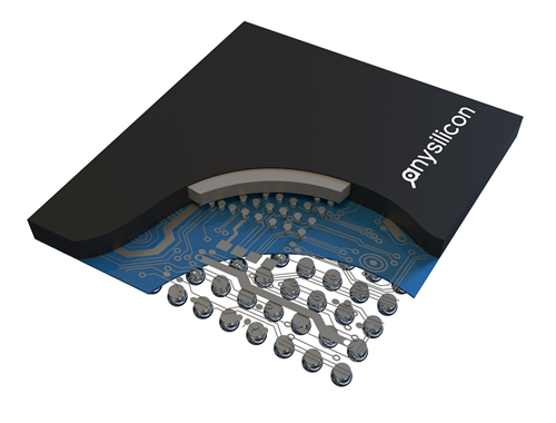
The substrate is not just a mechanical carrier. It directly affects package performance and manufacturability. Poor substrate design can create signal integrity issues, voltage drop, excessive noise, routing congestion, assembly problems, warpage, thermal limitations and reliability risks.
For advanced ASICs and high pin-count ICs, BGA substrate design should be considered early in the chip development process. Decisions such as die pad placement, bump map, package size, ball pitch, power and ground strategy and layer count can influence both the package cost and the final product performance.
A typical BGA substrate design project includes the following steps:
BGA substrate design depends strongly on the assembly method. A wire-bond BGA substrate is usually designed with bond fingers around the die area. Signals are routed from the bond fingers to the solder ball array. This approach can be cost-effective and is often used for analog, mixed-signal, microcontroller and moderate I/O-count ASIC devices.
A flip-chip BGA substrate is usually more complex. The die is connected directly to the substrate using bumps or copper pillars. This allows higher I/O density, shorter interconnect paths and better electrical performance, but it may require more substrate layers, tighter design rules and more advanced substrate manufacturing.
| Package type | Substrate routing | Main advantage | Typical use |
|---|---|---|---|
| Wire-bond BGA | Bond fingers to BGA balls | Lower cost and simpler assembly | Analog, mixed-signal, MCU, ASICs |
| Flip-chip BGA | Bumps or copper pillars to BGA balls | Higher I/O density and better performance | Processors, AI chips, networking, high-speed SoCs |
| Lidless BGA | Similar to flip-chip or advanced BGA routing | Improved thermal path and lower package height | High-performance and thermally sensitive devices |
To start a BGA substrate design project, the package design team usually needs several technical inputs. Providing accurate data early can reduce design iterations and avoid delays during assembly house review.
Typical inputs include:
Submit your BGA package requirements and AnySilicon will help connect you with relevant package design, substrate design, assembly and test vendors.
Request BGA Substrate Design Support
The substrate stackup defines the number of metal layers, dielectric thickness, routing channels, power and ground planes, via structures and manufacturing rules. Simple wire-bond BGA packages may use fewer layers, while high-performance flip-chip BGA packages often require more layers to support dense routing, power integrity and high-speed interfaces.
Common stackup considerations include:
BGA substrate design can become challenging when the die has a high I/O count, tight pad pitch, high-speed interfaces, multiple power domains, sensitive analog circuits or strict thermal requirements. Some of the most common issues include routing congestion, insufficient power and ground balls, crosstalk, poor return paths, impedance discontinuities and design rule violations.
Another common mistake is starting the package design too late. The die pad ring, bump map and package ballout should be planned together whenever possible. Early package planning can reduce substrate layer count, simplify routing and lower total packaging cost.
During the package development process, the assembly house or package design vendor may provide design databases for review. One common file type is the MCM file, which describes the package outline, substrate layout, pads and routing. MCM files are widely used in IC package design and are similar in concept to PCB layout databases.
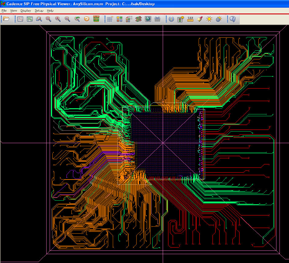
Engineers may use package design viewers to review the substrate layout, inspect routing, check package outline, review pad and ball locations, and support the signoff process. The Cadence Allegro Physical Viewer is one tool that can be used to view and plot package design databases from Allegro PCB Editor, Allegro Package Designer and related design environments.
Choosing the right BGA substrate design vendor depends on the package type, complexity, production volume, reliability requirements and assembly house flow. In many projects, the substrate design may be handled by the OSAT or package assembly house. In other cases, a specialized package design company may be used before the design is transferred to the assembly vendor.
When evaluating vendors, consider the following questions:
The cost of BGA substrate design depends on package complexity, ball count, die size, layer count, routing density, substrate technology, number of design iterations and analysis requirements. A simple wire-bond BGA substrate may be relatively straightforward, while a high-density flip-chip BGA with high-speed interfaces and multiple power domains may require more design effort and a more expensive substrate.
Key cost drivers include:
Use the packaging cost estimator below to get an indicative BGA packaging and assembly cost range. For a supplier quote, submit your email and project details, including package type, ball count, body size, annual volume, reliability level and target assembly region.
Get an indicative packaging cost range, then a detailed breakdown by email.
BGA substrate design is the layout of the package substrate that connects the silicon die to the solder ball array of a Ball Grid Array package. It includes routing, stackup, power and ground planning, ball map implementation and design rule checks.
A BGA substrate is similar to a small PCB, but it usually has tighter design rules, smaller geometries, higher routing density and stricter manufacturing requirements. It is part of the semiconductor package, not the system PCB.
The BGA substrate may be designed by the OSAT, assembly house, substrate supplier or a specialized package design company. The best option depends on the package type, complexity and production flow.
Common inputs include die size, pad ring or bump map, netlist, target package size, ball count, ball pitch, power requirements, high-speed interface constraints, thermal requirements and assembly house design rules.
Wire-bond BGA substrates route signals from bond fingers to package balls. Flip-chip BGA substrates route signals from die bumps or copper pillars to package balls. Flip-chip substrates are usually denser and more complex, but can support higher performance and higher I/O counts.
AnySilicon can help connect semiconductor companies with package design, substrate design, IC packaging and assembly vendors based on package type, technical requirements, location and production needs.
Looking for support with BGA substrate design, package layout, assembly or production? Submit your requirements and AnySilicon will help match your project with relevant semiconductor packaging vendors.