

I2C, or I squared C, stands for Inter Integrated Circuit. It is a serial bus that was designed and introduced by Phillips Semiconductor, now known as NXP Semiconductor, in 1982. The reason behind the creation of this synchronous, multi master, and single ended serial bus was to enable easy communication between various components on a single circuit board. As such, it is frequently and very commonly used to connect peripheral integrated chips and circuits to processors and microcontrollers residing on the same board. Not only is I2C being used for intra board connections, it has also been employed as a connector for different components linked through a cable.
I2C IP Core Benefits
The serial bus is extremely simple and produces a lot of convenience, which is what makes it a very popular choice. It is a protocol that essentially allows a master chip to communicate with a slave chip over a short distance. You also only need two wires or bus lines in order to exchange information between the two components of the link. It is a multi master system, meaning you can employ the use of multiple master chips and allow them to communicate with the slave ICs turn by turn over the same serial bus line. The hardware needed to implement an I2C system is also much less complex and simpler than what is needed for an asynchronous serial bus.
How Does I2C IP CoreWork?
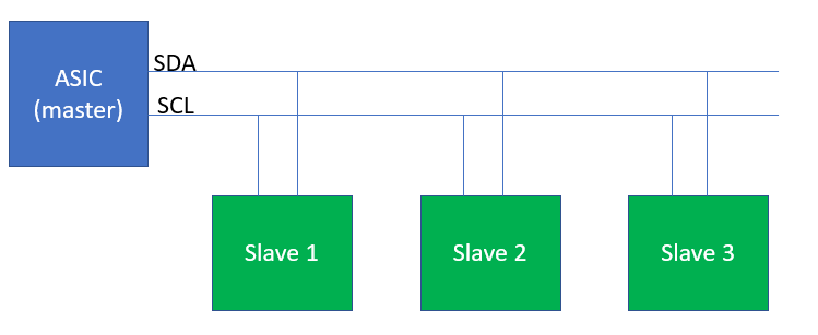
The way it works is that each I2C bus has two signals. The SCL signal is the clock signal, whereas the SDA is the data signal. Both these signals are pulled up with the help of a resistor. The master in the bus will be the one that generates the clock signal, although it can be delayed through clock stretching by the slave chips on occasion or when needed. Another major design feature of I2C buses is that while they can pull the signal line low, they cannot pull it high, resulting in an open drain system. As such, two devices can be connected through this bus without having to shift the circuitry of devices having voltage differences. If the voltage difference between the two components is much too high, you can also employ the use of a level shifter board to make it work.
Originally, the maximum clock frequency that an I2C serial bus could generate was topped off at 100 kHz but that has now been bumped up to 400 kHz, state known as the Fast mode. There also exists a High speed mode which allows you to go upto 3.4 MHz, as well as an Ultra fast mode which goes up to 5MHz.
Each slave device or chip in the system has a unique address comprising of 7 bits. These addresses can either be fixed or simply denote the lower bits of the address. The master device does not have an address as it is the one generating the clock signal. The master chip starts the communication process by generating the Start Condition, or S. After this comes the unique address for a particular slave chip. Depending on whether or not the bit 0 of the address was set to 0, the master chip will either write to the slave IC, read from it. The Stop Condition, or P, is generated by the master device once all the bytes have been read or written.


