

EDA or Electronics Design Automation refers to the use of computer programs and software tools for designing, simulation, layout, and verification of electronic systems. These are a set of powerful tools to physically design integrated circuits. As these ASICs are composed of billions of transistors, no human being is capable of designing these circuits without the help of automated tools. The electronic systems may be integrated circuits (ICs), printed circuit boards (PCBs), systems on chips (SoCs), etc.
Both analog and digital electronics designs are based of the use of computer programs at any level, that is from the transistor level to the architectural level. These tools assist a chip designer from RTL to GDS level (which is the last step in ASIC design flow before being sent to fabrication). EDA is not only limited to software solutions; it also includes hardware and other services used in the definition, planning, designing, simulating, implementation, verification of the design, and manufacturing of the devices. As integrated circuit technology has grown, the chip design introduces new challenges to optimize in terms of efficiency, power consumption, cost-effectiveness, size, and many more. And there are several different tools available for each step. In the past decades, there have been three major EDA companies. As the license of these tools is pricey, an open source tooling has become a fact in the industry.
The manual design of integrated circuits where thousands of transistors are on a single chip is practically impossible. These EDA tools are indispensable to cope with the complexity of very large-scale integrated circuits (VLSI). On the other hand, the cost of these tools is the stumbling block that a small team will never be able to design their chip. For this reason, freeware EDA sources are getting popular among researchers and students to learn about ICs and fabricate their chips.
Whenever we hear the term “open source software” we don’t believe we get quality for free. But don’t be fooled. It is really impressive to look at the progress of open source EDA for ASICs. Several initiatives and conferences have been launched in the past few years, creating an interesting momentum. One of The most important key sponsors of this program is DARPA (the U.S. Defense Advanced Research Projects Agency).
Although there are many powerful tools available, they are not freely available to students or small-scale teams. In the past, some open source tools were available, but they didn’t meet the industry standard. These tools were unable to produce something that met industry requirements. The biggest issue with closed-source software is access. Everyone has to sign up and purchase for a short period. The field has revolutionized in terms of helping people to educate themselves.
Many open source tools are available on the market. These tools are available for everyone and all ends. People are free to distribute software copies. Developers have the freedom to modify, improve and release the improvements to the public.
Pick a stage + optional keyword. See top 5 instantly.
Need a vendor-supported flow (PDK, integration, sign-off)? Contact AnySilicon.
The software tools listed below, follow the design flow. Various steps are required to develop an IC. A digital circuit is described in the HDL format, synthesis, place and route, and post-layout simulation.
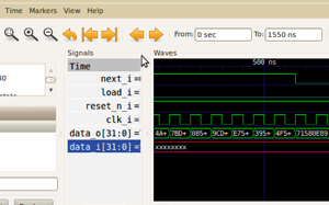
CppSim: has been actively used since 2002. It is used for commercial and academic purposes. It performs system-level simulations of mixed-signal circuits. It automatically produces, compiles, and executes C++ code per the schematic design you produce.
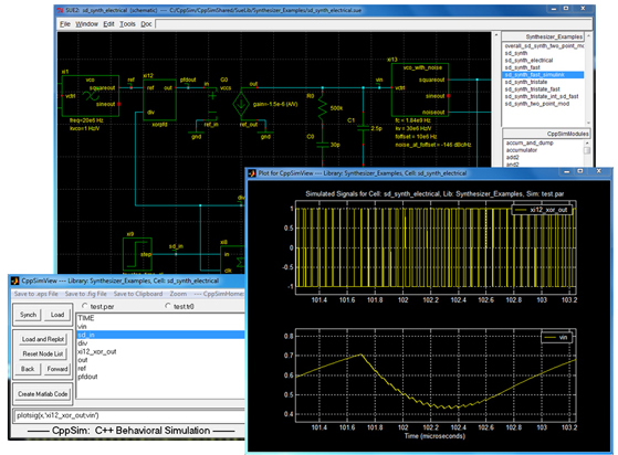
CppSim schematic and waveform viewer
Electric: among one the powerful CAD systems which can handle different types of circuit design tasks including MOS, Bipolar, schematics, printed circuitry, hardware description languages, etc. It can analyze design rule checking, simulation, and network comparison. It can perform synthesis as well, like routing, compaction, silicon compilation, PLA generation, and compensation.
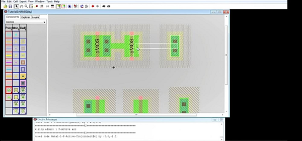
Layout design in Electric
eSim: an integrated tool built from open source software such as KiCad, Ngspice, Verilator, Makerchip, GHDL, and OpenModelica. It is an EDA tool for circuit design, simulation, and analysis.
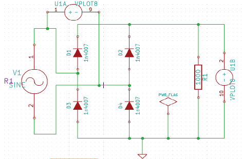
Schematic capture using eSim
IRSIM: a tool for simulating digital circuits. It is a switch-level simulator, where transistors are treated as ideal switches. In this simulator, the circuit under simulation can be modified and then incrementally restimulated. It maintains the history of circuit activity and only restimulates the part of the circuit that deviates from its history.
Electric has a built-in simulator, Stanford’s IRSIM. It uses an RC simulation model (by default) as well as a linear simulation model to simulate the digital circuit at the gate level. The built-in IRSIM Simulator for Electric is shown in the picture below.
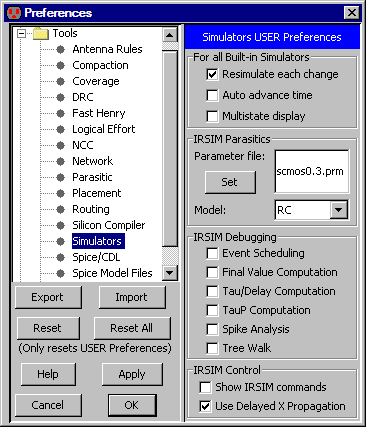
IRSIM simulator (dialogue box in Electric)
Mosaic: Analogue integrated circuit designs can be created and simulated using the tool mosaic. It emphasizes a cutting-edge, user-friendly interface, immediate design feedback, design reuse, verification, and automation. Regardless of your internet connection, Mosaic will remain quick and accessible and synchronize your modifications when you reconnect.
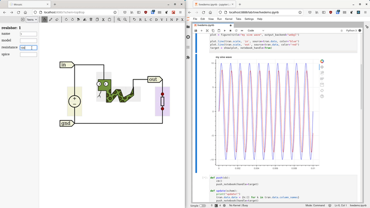
The user interface in Mosaic
Ngspice: An open-source mixed-signal SPICE simulator. ngspice has a command line input interface and plots the waveforms. This tool offers active development and improved stability. ngspice is based on three open-source free-software packages: Spice3f5, Xspice, and Cider1b1:
SPICE is the origin of all circuit simulators.
XSPICE provides additional C language models that help in simulations of digital circuits with the fast-driven algorithm.
Cider1b1 couples the circuit-level simulator to the device simulator to provide enhanced simulation accuracy (but with increased simulation time).
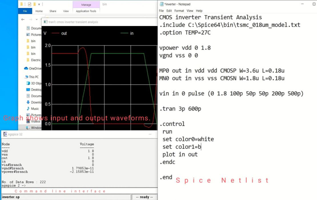
Ngspice command line interface, spice netlist, and waveform viewer
QUCS(Quite Universal Circuit Simulator): a well-advanced circuit simulator that supports all kinds of simulations like DC, AC, s-parameter, noise, transient analysis, etc. It allows importing existing SPICE models as well.
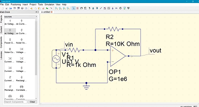
Schematic diagram view in QUCS
X Circuit: The schematic diagrams drawn from the schematic capture program do not produce an image that is suitable for publication. Engineers have to draw the schematic with the help of general-purpose drawing tools. It is a drawing tool that is specifically for circuits only. It can produce high-quality schematic diagrams and other figures that are suitable for publication purposes.
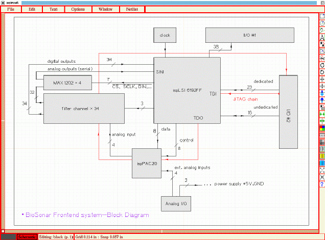
Schematic diagram in XCircuit
Xschem: a schematic capture program for VLSI and ASIC design.
In addition to supporting SPICE, Verilog, and VHDL netlist generators, XSCHEM provides a schematic editor for digital, analog, mixed-mode, and VLSI/ASIC designs. It supports the following four netlist formats.
Simulation data on Xschem
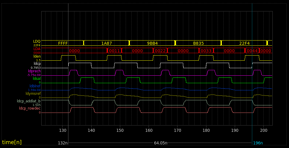
XYCE: a SPICE-compatible software, written in C++ and using MPI (Message Passing Implementation). It also includes Trilinos ( Sandra’s open source library), which includes KLU direct solver and many more circuit-specific solvers.
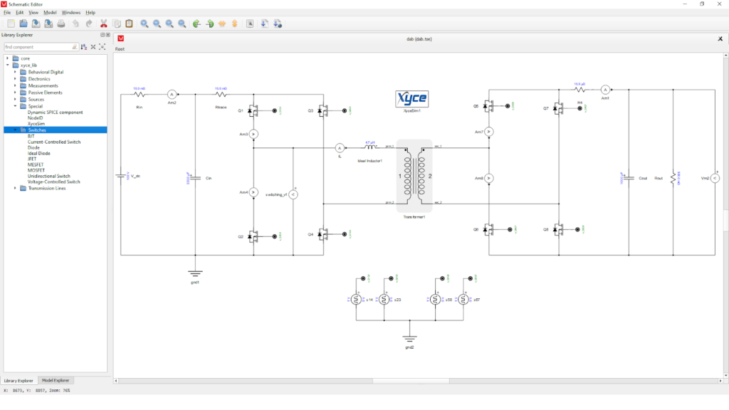
XYCE User interface
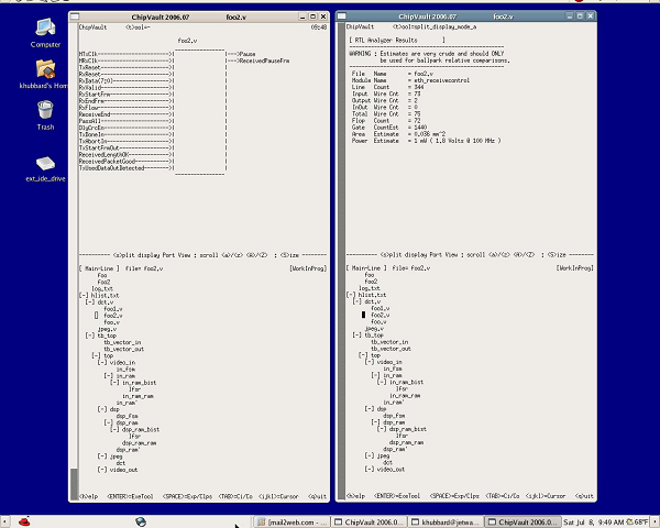
ChipVault: an organization tool for HDL. It allows for hierarchical file navigation, sorting, and editing.
EDA Playground: a free web application for HDL (including Verilog, system Verilog, VHDL, and other HDLs) simulations and synthesis. It generates a browser-based waveform viewer after a successful simulation. It is easy to use because no download is required and code sharing is easy.
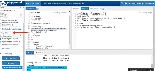
EDA Playground in a browser
GHDL: translates VHDL files directly into machine code and hence faster compilation and analysis of code than any other interpreted simulator.
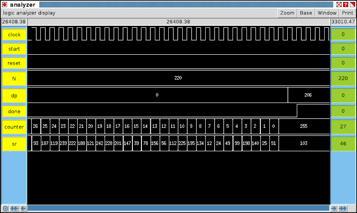
Waveform viewer
Icarus Verilog: a compiler for Verilog HDL as described in the IEEE-1364 standard. With the help of written Verilog code, it compiles the code into some target format. This tool supports a waveform viewer named GTKWave.
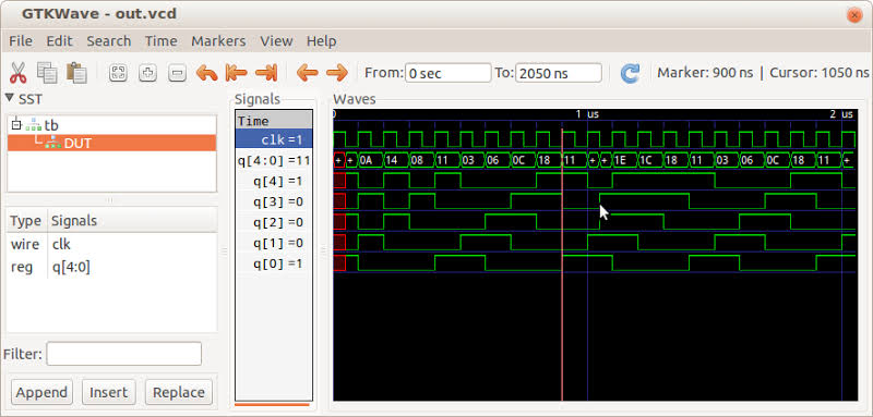
Simulation of a sample code using Icarus Verilog
Migen: a python-based tool that applies advanced software concepts like OOPs, and metaprogramming in the VLSI design process and building complex digital hardware. It is a brand new programming language based on FHDL
Yosys: a synthesis tool that can handle Verilog code and can synthesize complex projects as well.
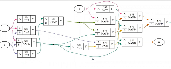
Synthesis using Yosys
Fairly Good Router: a software for routing, based on Lagrange multipliers. It is an academic tool and it is based on similar routers used on industrial levels.
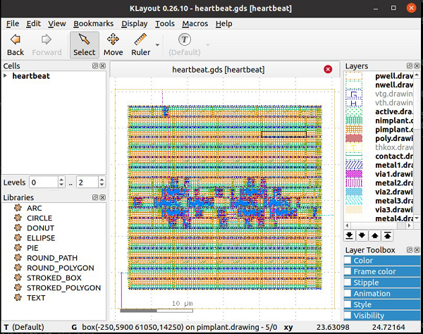
KLayout: KLayout is an editor that helps with the layout. It is also helpful in changing and creating GDS and OASIS files.
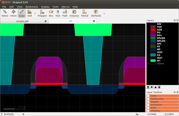
sample cross-section
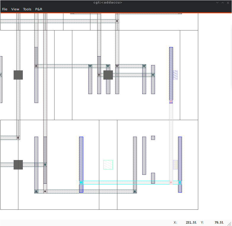
Magic: is considered one of the easiest tools for circuit layout. This tool supports LVS and DRC as well.
Layout using Magic
QRouter: a tool for routing based on the standard Lee maze routing algorithm. It supports LEF and DEF formats as input and output.
Layout generated by QRouter
OpenSTA: is used to verify the timings of a circuit at the gate level.
OpenTimer: A high-performance, commercial-grade timing analysis tool. It helps IC designers with its interactive analysis to verify circuit timings. It supports both path-based and graph-based timing analysis. It is relatively a new tool that supports industry-standard format support like .lib, .v, .spef, and .sdc.
HiTas: Another tool for static timing analysis.
Netgen: is a verification tool for comparing a layout to a netlist. To ensure this physical verification and LVS is carried out. Netgen version 1.5 is considered a commercial-grade tool.
Dragon: is an effective tool for standard cell placement for variable and fixed die ASIC design.
Gdsfactory: Since gdsfactory is entirely written in Python, some Python concepts are necessary. It is built on top of KLayout, gdspy (Python library for producing GDSII files), and Phidl (Python module for GDS layout and cad geometry).
There are many EDA tools, they are individual applications that help in designing digital systems. There are several other flow-based tools available.
These toolsets integrate numerous tools like schematic editor, circuit simulator, schematic driven layout generator, layout editor, layout verification, and parasitic extraction. It is preferable to use them because there are many stages, and each stage is followed by sub-stages. Some software allows swapping data while others don’t.
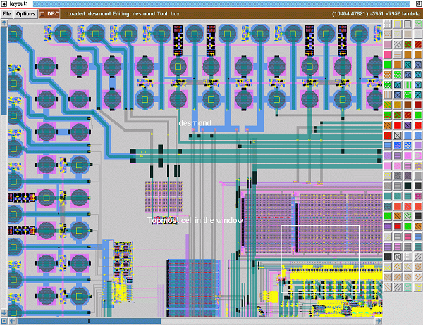
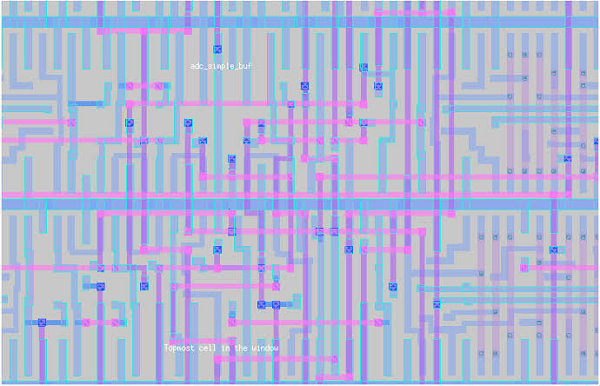
Alliance/Coriolis VLSI CAD Tools: Alliance / Coriolis is a free software toolchain for VLSI design. The input is HDL (Verilog or VHDL) and the output is GDSII, which is all set for ASIC manufacture.
Layout using Alliance
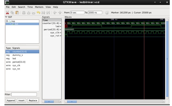
Qflow: Provides a set of tools and methods to turn an HDL code (written in Verilog or VHDL) into a physical circuit. It is capable of handling sub-systems like host-to-device communication, signal processing, arithmetic logic unit, etc.
Waveform viewer Qflow 1.3
OpenLane: An automated VLSI design flow for digital synthesis. It is a collection of open-source tools. It performs all the tasks from RTL to GDS-II with the help of a predefined set of commands for design explanation and optimization. It has two modes.
OpenLane flow consists of several stages like:

OpenLane command line interface
OpenROAD: is a flow of open source tools for ASIC design. The whole flow is automated for digital SoC layout generation, focusing on the RTL-to-GDSII phase of system-on-chip design.
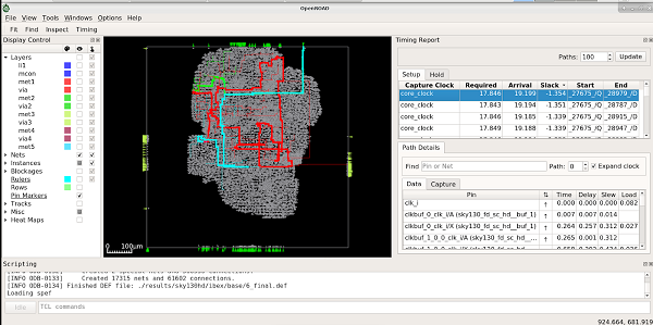
OpenROAD GUI
OSS CAD Suite: OSS CAD Suite is a component of YosysHQ’s Tabby CAD Suite. There are tools available for synthesis, hardware verification, place and route, programming, and testing.
Silicon Compiler: automatically translates source code to hardware design. There are three steps.
Layout using SiliconCompiler
The world of chip designing is successful in creating physical designs using free tools. Now the influencers are moving towards open source hardware. Until June 2020, the open source community doesn’t have any solution for the PDK. PDK is only requested from the foundry. After getting PDK, we would be able to go for ASIC design. The first-ever open-source PDK has been introduced by Google. It is Sky 130 PDK. Now, the whole design is open source, from tools, PDK, IP libraries, and standard cell libraries to analog blocks.
With open source tools, Google allows you to manufacture without any cost. Google along with Efabless and SkyWater Technology created the first open-source PDK known as SKY 130, based on 130nm CMOS technology. The Google-sponsored MPW shuttle program is free for open-source designs (under certain terms and conditions). Under this program, open source designs will be fully funded by Google. The cost of fabrication, evaluation, boards, and shipping all are sponsored by Google. Every month, you have an opportunity to submit your design. If your design is selected by the shuttle program, then you are going to get your chip for free!
The idea of open source means to involve many users (and hence the developers as well, which are ready to fix the bugs and offer improvements). So, there is larger community support either in the form of enhancement features or development processes. The same is true in this case as well. A vital role is played by nonprofit organizations in the sustainable development of open source EDA tools and services. Engineers around the world come up with new ideas, and inspiration. Some years ago, this chip designing industry was ruled by only big companies and their audiences were also enterprises only. This freely available software helps anyone either a student, a young engineer, or a hobbyist to model the behavior of their concepts, model, and analyze the complexity of the design, EDA helps to eliminate problems at the same time. All these steps are necessary before the fabrication process. Because it is a futile attempt to build it first and fix it later.
References
[1] Ibtida: Fully Open-Source ASIC Implementation of Chisel-Generated SoC.
[2] Flaherty, Nick. “RISC-V Chip Designed with Open Source Tools Renews Europe.” EENewsEurope, 9 May 2022, https://www.eenewseurope.com/en/risc-v-chip-designed-with-open-source-tools/.


