

The world we are living today is full of complex digital systems that we need to rely on. They are becoming more sophisticated and infinite complex. Safety and security of these systems are of critical importance and repercussions of malfunctions can be catastrophic. Even with rigorous testing, there can be numerous ways to go wrong. However, to minimize these issues, different strategies are employed by verification engineers to achieve the goal – completeness of verification space by ensuring that a design implementation meets its specification.
”Formal verification uses mathematical models/methods to prove or disprove the correctness of the system’s design with respect to formal specifications expressed as properties.”
Simulation VS Formal: Simulation tests the design whereas formal proves it.
In a more orthodox (still most used) way of verifying a digital design is using simulation-based verification methodology. In simulation-based verification, the inputs of the DUT are derived with certain (range of) values and outputs are observed. Once outputs are captured, they are compared against the reference model for correctness and completeness check. This requires a specific testbench to be developed for a certain DUT to drive/capture signals and compare results. Moreover simulation-based verification takes ages to complete the verification space. Imagine verifying a 32 bits counter or 32 bits multiplier. To cover complete verification space of these designs, this will take 2^32 and 2^64 (two 32bits values in multiplier) simulation cycles respectively which can end up in days (if not weeks) even with best-in-class simulators.
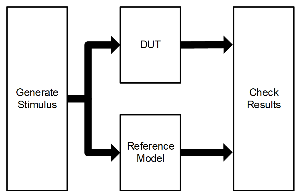
Figure 1: Simulation Verification Methodology Flow
Formal verification methodology uses the specifications/constraints (written as properties) and uses mathematical properties to prove (or disprove) that design is compliant to those requirements. If a property specified for the design is found to be not true, the tool will provide a counter example with all inputs required to the DUT to find the issue.
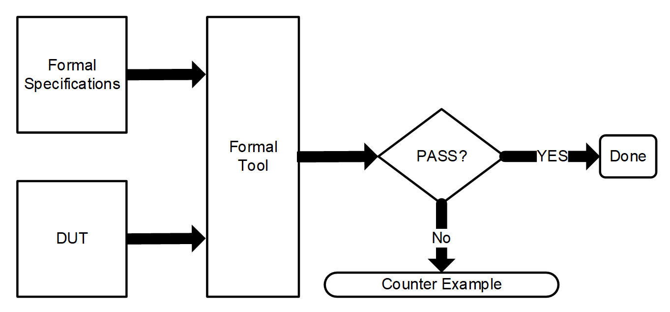
Figure 2: Formal Verification Methodology Flow
The formal input for the specifications of the design is usually defined using System Verilog properties. The properties can be of different types.
We can look at an example how formal tool can be used to verify a certain part of the design. Let us consider a 2×1 MUX with a truth table as below.
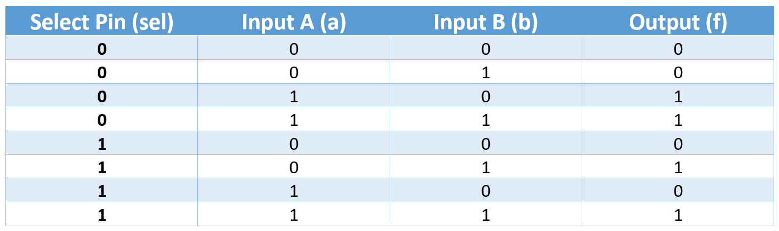
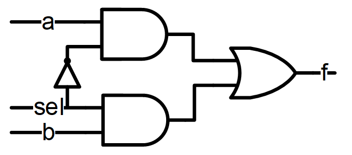
The design can be defined as
f = a.sel’ + b.sel
Here:
‘ represents the NOT operator
. represents the AND operator
+ represents the OR operator.
In order to verify this circuit with simulation, one has to drive all 8 different input patters to cover complete state space. However, in order to verify this circuit with formal tool, one has to write specification of the circuit with properties as described below.
P1: assert property (!sel |-> f ==a)
P2: assert property (sel |-> f ==b)
The first property P1 defines the design intent that whenever sel pin is active low, output f should be equal to input a. Similarly, second property P2 defines that whenever sel pin is active high, output f should be equal to input b. The two properties can be viewed as complete specification for the design.
With these two properties and DUT (2×1 MUX) as inputs to the formal tool, the formal tool will try to prove/disprove the above properties for complete state space (all valid input/output combinations). The tool will try to find a CEX (counter example) for the above properties. If it cannot find a CEX, the above properties can be viewed as true and thus design meets specifications.
One of the CEX (opposite to property P2) will be to check if sel && !(f == b) can be satisfied. This means when SEL pin is high, output f equal to b will not hold true.
Now let’s assume that there is a bug in the design where lower AND gate is replaced by XOR gate. Now the tool will try to find inputs so that CEX is satisfied and indeed it can find the input pattern where the CEX is satisfied and thus property P2 does not hold true. The tool will provide this precise stimulus so that bug can be found and fixed by the designer.
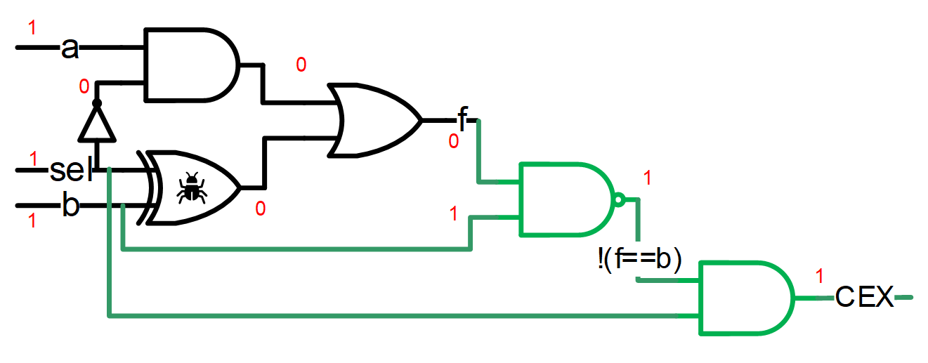
Figure 3: Formal way to provide Counter Example (CEX)
There are many tools in the industry which uses formal methodology to achieve particular purpose.
Synopsys: Synopsys provides VC Formal tool which covers wide range of formal applications such as Assertion based verification, connectivity verification, sequential verification, etc. There is VC LP which is mainly used to verify formally the low power design intent.
Siemens/Mentor Graphics: Siemens/Mentor Graphics Questa tool also provides formal verification specific applications such as Questa Connectivity check, Questa post silicon debug, Questa property check, Questa Register check, etc.


