

The Internet of Things (IoT) is the interconnection of millions of autonomous devices to the internet. These devices collect data on physical parameters and processes and report those to the network. Some autonomously, or by network command, provide outputs that control other equipment and systems.
There are a wide range of applications for IoT devices including infrastructure, utilities, home automation, personal medical, vehicle, industrial and more. The full range of potential applications has not been conceived. The market for IoT devices will explode as additional applications are addressed.
There will be many new ideas in this field, and a great number of these will come from companies without background or experience in developing high-tech devices and equipment.
Many of these new IoT inventions will be implemented with a single system on a chip (SoC) to provide the highest level of integration and conservation of area. As numerous new companies enter into the market with their own ideas for IoT, many will begin to face the challenges of IoT SoC development.
One of the most important aspects of developing a custom SoC for an IoT application is differentiating your product from other competitors in the market. Figure 1 is a block diagram showing many of the typical functions that can be included in an IoT SoC design. You can see in the bottom portion of the diagram that many of the functional blocks that are used in a typical SoC are either standardized or very highly commoditized. Utilizing commercially available IP blocks for these functions brings several benefits but no differentiation. In fact, for those blocks that are completely standards driven (for example a USB interface) it is nearly impossible for there to be any differentiation.
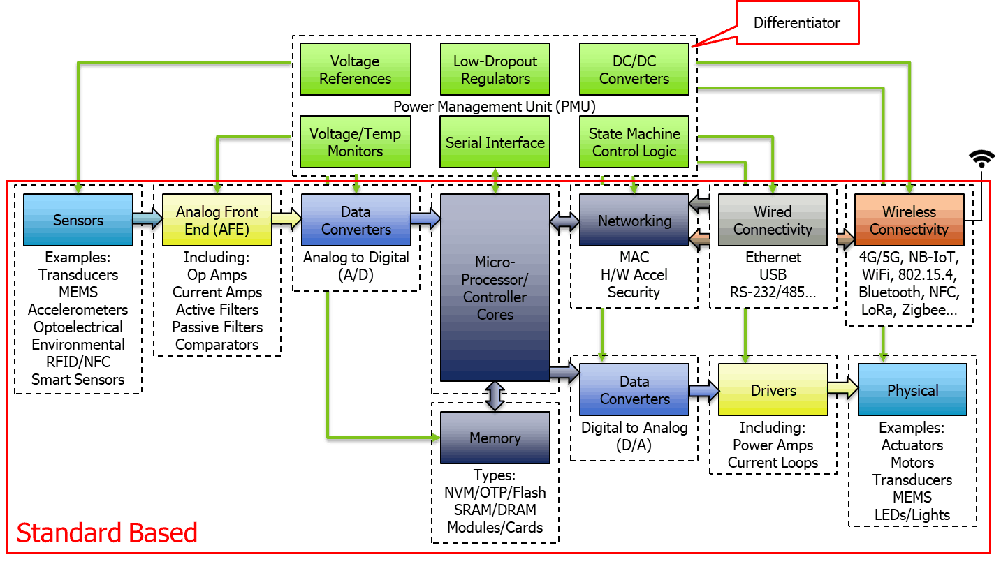
Example IoT SoC Block Diagram
The high-performance analog and mixed-signal blocks, however, can be an area for customization and differentiation. Most IoT SoC designs are implemented in small-geometry processes (55 nm and smaller) to take advantage of both power and die area savings. However, there are significant challenges of analog circuit design in small process linewidths due to transistor mismatch and leakage. Vidatronic has significant experience in overcoming the difficulties of designs in advanced-processes (down to 7 nm), and using our IP can help you get to market faster with lower risk and less cost than trying to design these circuits in house.
The power management blocks, in the upper portion of the block diagram, are analog and mixed-signal circuits specialized for the application at hand. There are several different types of blocks represented in the power-management section of the block diagram. The first is the low-dropout linear (LDO) voltage regulator. LDOs are frequently used to supply the many different voltage rails required on the SoC, and to isolate the internal SoC circuitry from external sources of noise on the circuit board power supply rails.
Most LDO circuits require an external capacitor on their output for various reasons. The use of output capacitors for every LDO in an SoC system, however, can consume significant amounts of board real estate, add cost to the system, and decrease reliability due to solder joints for the extra external components as well as due to capacitor failures on the PC board. Frequently, external LDO ICs are used because of the difficulty of integrating this analog function onto the die. Vidatronic has an LDO technology, Noise Quencher®, which can be integrated onto the die and does not require an output capacitor. Vidatronic IP blocks are available in the process nodes typical for IoT SoC development and therefore they can be implemented on the IoT SoC die to supply all of the various internal power voltages necessary.
One problem with using LDOs to generate low voltages from an incoming power supply is that they burn power relative to the amount of voltage-drop from the input to the output. If you have a relatively high voltage drop, LDOs are not efficient. In this case, it is better to use a dc-to-dc converter that can achieve significantly higher efficiency than an LDO. The drawback to a dc-to-dc converter is that it is a switched-mode circuit and can induce switching noise into its output voltage. Extremely noise-sensitive circuits should not be supplied by dc-to-dc converters. One possible solution to overcome this is to cascade a dc-to-dc converter for efficient voltage-drop followed by an LDO to clean up the supply noise.
There are two types of dc-to-dc converter technologies: standard inductor-based dc-to-dc converters which require an external inductor and capacitor to create the dc output level and switched-capacitor dc-to-dc converters which can be implemented with on-die capacitors but cannot supply as much current as inductor-based solutions. Vidatronic has both types of technologies available as silicon proven IP.
Additionally, dc-to-dc converters can be used either in buck mode, for use where the output voltage is lower than the input voltage, or in boost mode where the output voltage is higher than the input voltage. There are also combination buck-boost mode dc-to-dc converters that automatically supply the correct output voltage regardless of the input voltage. This is particularly common in battery-powered applications. When the battery is connected to a charger or is fully charged, the battery voltage may be higher than the required voltage of the load circuitry. Then as the battery becomes discharged, the battery voltage is lower than the required voltage of the load circuitry.
Vidatronic has a switched capacitor buck-boost dc-to-dc converter IP block that does not require any external components. It can generate the required output voltage regardless of whether the input voltage is above or below the required output voltage.
Another type of power management block is the bandgap voltage reference. Voltage references are a necessary part of the power management system in nearly any IoT SoC device. Voltage references are commonly used as a reference for various op amps, comparators, data converters and many other analog and mixed-signal functions. Three desired characteristics in a voltage reference include low power consumption, high accuracy, and good power supply noise rejection. Vidatronic has a leading voltage-reference IP technology that can achieve industry-best 0.3% accuracy (trimmed) with less than 10 microamps (µA) of current consumption and better than 80 dB of power supply noise rejection. We also have extremely low power (IQ < 100 nA) voltage references, suitable for always-on micropower applications, with very good accuracy and noise performance.
There are many other foundational analog circuit blocks that are commonly used in power management applications. These include oscillator, voltage monitor, temperature sensor and power-on reset (POR) circuits.
Although there are many ways to implement oscillators, for power-management functions they are generally of either the relaxation or the ring architecture. While neither are novel, implementing them to reliably start and oscillate at the correct frequency across process, voltage and temperature (PVT), with reasonable power consumption, can be challenging in advanced fab processes.
Voltage monitors and temperature sensors are frequently used for failsafe reasons, flagging the controller to shut down the system when a limit has been reached. Key parameters are accuracy and hysteresis.
Power-on reset (POR) circuits are usually a necessary part of any IoT SOC design, to hold off the start-up of logic circuits until the power supply voltages have reached an adequate level to achieve valid logic states in the system.
The use of these various power management blocks on an IoT SoC generally is not independent. Frequently what is required are very carefully controlled power-up and power-down sequencing of the various supply rails and the ability to shut down certain power supplies during specified low-power operating states of the SoC. To control the various power-management blocks, usually a logic state machine is added to ensure the right timing and sequencing of power supply bring up and shut down and to establish the various low-power states. This logic state machine is often controlled by a microcontroller or microprocessor through a serial interface (e.g. I2C). The careful development and testing of these logic circuits and their interface with the analog power management blocks is not trivial.
Vidatronic has these various technologies available and has many years of experience in the correct implementation. Generally, grouping all of these various power management blocks together with some control circuitry and an interface for external control is what is known as a power management unit (PMU).
Utilizing Vidatronic IP and custom circuitry for your IoT SoC development can help get you to market faster, with differentiated product features and performance. Our experience reduces your overall project risk. For more information on our patented technology, please visit our website. To read more a more in depth introduction to power management in IoT SoC development, download the full white paper.


