
This is a guest post by Dolphin Integration which provides IP core, EDA tool and ASIC/SoC design service.
The frequency of the very large Systems-on-Chip continuously increases over the years. Operating frequencies of up to 1 GHz are common in modern deep sub-micrometer application specific integrated circuits. The verification of timing in VLSI circuits is achieved by means of static timing analysis (STA) tools which rely on data described in the cell libraries to analyze the circuit. The characterization of the individual cells in cell libraries is therefore highly critical in terms of accuracy of the STA results. Inaccurate characterization of constraint timings causes the STA results to be either overly optimistic or pessimistic. Both cases should be avoided as the optimistic case can cause a fabricated circuit to fail, whereas
the pessimistic case unnecessarily degrades circuit performances.
This article describes the setup/hold pairing for the standard cells and proposes a new method to characterize it accurately. The first part discusses the setup/hold constraints and the existing solution to model the setup/hold interdependence. The second part emphasizes on the Dolphin Integration solution to determine the setup/hold interdependence and the last part applies the new solution on the pulsed latch (spinner system).
The setup time for a sequential cell is the minimum length of time during which the datainput signal must remain stable before the active edge of the clock (or other triggered signal) to ensure correct functioning of the cell.
The hold time for a sequential cell is the minimum length of time during which the data-input signal must remain stable once the edge of the clock is activated (or other triggered signal) to ensure correct functioning of the cell.
Figure 1 illustrates setup hold times for a positive-edge-triggered sequential cell.
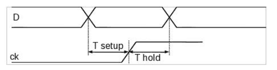
Measurement methodology: Setup constraint values are measured as the delay between the time when the data signal reaches 50% of Vdd and the time when the clock signal reaches 50% of Vdd.
Bisection: The bisection method is an algorithm used to search for the solution of a function. The method consists in repeatedly dividing the range of the input signal into two parts and then selecting the sub-range in which the solution of the output signal is found. The algorithm stops when the tolerance criteria for the output signal is reached.
Pass-fail: The Pass-Fail method is a particular case of the bisection method where the result for the output signal must PASS for one limit value of the range of the input signal and must FAIL for the other limit. Figure 2 presents the Pass-Fail method.
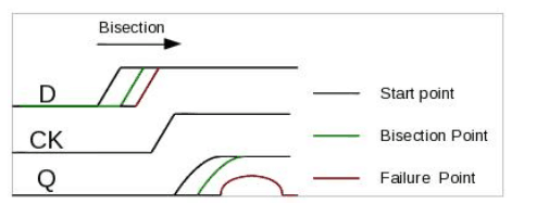
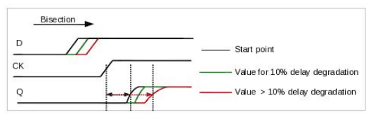
Push-out: The cell is considered functional as long as the output reaches its expected value and the delay of the output does not exceed the reference duration by more than X% (pushout methodology). The reference delay is the one measured with a large setup time (ideally
infinite). X is called hereafter the “percentage of degradation” (see Figure 3).
Minimum hold time and minimum setup time: The minimum setup time is measured when the hold time is considered infinite. In the same way, the minimum hold time is measured when the setup time is considered infinite.
The setup time depends on hold time and vice-versa which means that an interdependence exists between setup and hold.
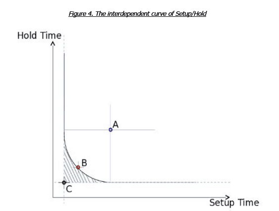
Figure 4 presents the interdependent curve of Setup-Hold. Whatever the point selected on the curve the output signal delay is degraded by X% (push-out method). The hatched zone represents the zone where the cell does not meet the bisection or functional criteria. Point C
corresponds to the minimum setup and minimum hold which is provided by most standard cell library providers. This point, found in the hatched zone, is very optimistic as it is far from the safety barrier represented by the curve. In some cases, this characterization may have
an impact on the functionality of the circuit for paths with relatively small setup and hold slacks. In fact, the distance between the characterized point and the curve represents the required positive slack for setup and hold at STA level. The constraint is hidden to the SoC designer as library providers do not provide those margins and do not elaborate on the impact of their characterization choices. Point A is found in the security zone but it is very pessimistic/negative with respect to the performance of the circuit. There is a considerable reduction in the circuit speed. Point B is the optimum point because it has the advantage of being located at the frontier of the security zone, which means there are no hidden
constraints, without leading to any important reduction in performance of circuit (in terms of speed). So, Dolphin Integration, as library provider, has setup a characterization methodology to take the interdependence into account while characterizing optimally both the setup time and the hold time on the frontier of the functional region (point B in Figure 4).
Methodology of determination of the setup/hold curve To determine the setup-hold pair on the curve, we use the bisection algorithm linked to the push-out criteria. The X% percentage of degradation of the push-out is shared between the setup time XS% and hold time XH%. This determination of setup and hold pair can be performed in two distinct ways: by injecting measured setup time in hold time determination
or conversely by injecting measured hold time in setup time determination as detailed below. To inject setup time in hold time determination, we measure the setup time with an infinité hold time using the XS% push-out criteria. Then, the hold time is characterized with the
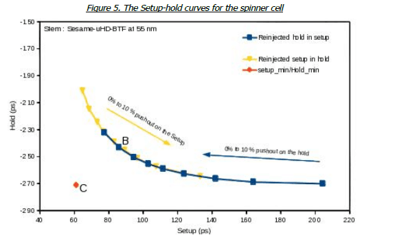
XH% push-out criteria while re-injecting the measured setup time. The result is shown below as the yellow curve of Figure 5.
To inject hold time in setup time determination, we measure the hold time with an infinité setup time using the XH% push-out criteria and then the setup time is characterized with the XS% pushout criteria while re-injecting the measured hold time. The result is shown below as the blue curve of Figure 5. With this method and the appropriate parameters of degradation, we characterize point B in Figure 4, whereas by adding fixed margin to the determined setup and hold time, the pessimistic point A of Figure 4 is obtained.
The spinner system is a particular design of the pulsed latch developed by Dolphin Integration [1]. The pulsed latch represents an alternative to the conventional flip-flop for ultra high-density logic design.
The pulsed latch is denser than the flip-flop. The replacement of conventional flip-flops by pulsed latch presents a 10% area saving after P&R for both mature and Advanced technological nodes. To benefit the advantage of the pulsed latch (spinner system) mastery of the constraint timings characterization is required as illustrated with the P&R on the benchmark (Motu-Uta [2]).
The methodology of characterization with re-injection is illustrated with the Dolphin Integration standard cell stem SESAME-uHD-BTF at 55nm process (Figure 5). The choice of point B(see Figure 5) is a compromise for the Setup/hold pairs that provides a good result in both timing and area on the Motu-Uta benchmark. The degradation timing between the C, B points, degrades only of 1% of the circuit frequency. As a result, the circuit will be more reliable.
This article shows the importance of the choice of the characterization methodology for the Setup-Hold pair. The solutions proposed by Dolphin Integration provide the best compromise between circuit speed and reliability.
This paper showcases the study on the Setup/Hold inter-dependence. It examines different existing methods for characterization and presents a new method to determine the Setup/Hold pairing for Standard Cells. This new method developed by Dolphin Integration is applied particularly on the pulsed latch (spinner system) in order to obtain the best compromise between circuit’s speed and the reliability.
[1] ChipEstimate – 2013-02-26 – Spinner System: optimized design and intégration
methodology based on pulsed latch for drastic area reduction in logic designs
http://www.chipestimate.com/tech-talks/2013/02/26/Dolphin-Integration-Spinner-
Systemoptimizeddesign-
and-integration-methodology-based-on-pulsed-latch-for-drastic-area-reductioninlogic-
designs/Dolphin-Integration
[2] ChipEstimate – 2010-02-23 – Choosing the best Standard Cell Library without falling into
the
traps of traditional -benchmarking methods
http://www.chipestimate.com/tech-talks/2010/02/23/Dolphin-Integration-Choosing-the-best-
Standard-Cell-Library-without-falling-into-the-traps-of-traditional-benchmarkingmethods/
Dolphin-Integration
SESAME TSMC 55 eF
http://www.chipestimate.com/log.php?from=%2Fip.php%3FUltra%2Bhigh%2Bdensity%2B6
–
Tracks%2Bstandard%2Bcell%2Blibrary%26id%3D34413%26partner%3DDolphin
%2520Integration&logerr=1
SESAME TSMC 130 BCD
http://www.chipestimate.com/log.php?from=%2Fip.php%3FUltra%2Bhigh%2Bdensity%2B6
–
Tracks%2Bstandard%2Bcell%2Blibrary%26id%3D34359%26partner%3DDolphin
%2520Integration&logerr=1
SESAME SMIC 130 G
http://www.chipestimate.com/log.php?from=%2Fip.php%3FUltra%2Bhigh%2Bdensity%2B6
–
Tracks%2Bstandard%2Bcell%2Blibrary%26id%3D35732%26partner%3DDolphin
%2520Integration&logerr=1
Click here to learn more about Dolphin Integration products and services.


